Translate

Thursday, December 13, 2012

Elenco's XP-720K Power Supply Kit

The XP-720K power supply features three solid-state DC supplies. Two DC supplies are positive and negative 1.25 - 15 volts at 1 ampere. The third has a fixed 5 volt at 3 amperes. There is one integrated circuit regulating each DC supply for a total of three integrated circuits. In addition, the supply has two 6.3 volts alternating current supplies that are taken directly from the transformer; moreover, the transformer steps down the 120VAC input to 17VAC, which is delivered to the AC to DC converter. This converter consists of two diodes and a 2200 microfarad capacitor. To conclude, this supply was fun to build and is about all I would need on my work bench. I think any lab or work bench would find it useful. Lastly, I like the small profile and the look of the control panel. Below are the assembly pictures, and the testing information for the power supply. I also included the watt reading's of the supply during the testing phase.  

 Assembly
Heat sink with IC and transistor
PC Board completed 
Transformer wired to fuse and switch
PC Board wired into Transformer, Binding Posts, Potentiometers, ICs, and Transistor
Completed XP-720 Power supply. 

Testing
Testing the Positive Variable DC 1.25-15V low end
Testing the Positive Variable DC 1.25-15V high end
Testing the Negative Variable DC -1.25- -15V low end
Testing the Negative Variable DC -1.25- -15V high end
Testing the 5VDC 
Testing first post 6.3VAC
Testing second post 6.3VAC
 LOAD TEST #1

The first test is to set the voltage at 10V and connecting a 10 ohm, 10 watt resistor from the output to ground. The output should not change more than 0.20 V. The results was a change of - 0.13 --acceptable. The watt reading was not part of the testing, but I recorded how many watts the power supply draws from the outlet, which was 37.7 watts.  
Dialed in load test voltage for 10 ohm, 10 watt resistor
Load tested at 9.88VDC 
 LOAD TEST #2

The second and last load test was the 5VDC. This test required connecting a 2.5 ohm, 12 watt resistor from the output to ground. The output should not change more than 0.20V. 
The result was a change of - 0.11 --acceptable. And the watt reading was 37.2.
Reading before load test of 2.5 ohm, 12 watt resistor
Load tested at 4.84VDC

Wednesday, December 12, 2012

Elenco's PK-201 Experiment #50: Logic Combination

This is the last circuit of the first part (PK-101) of the PK-201 course. This circuit is a combination of some of the other digital gates. There is one output that uses a LED, and three inputs X is the red wire, Y is the blue wire, and Z is the green wire. In the video, I show the work book's truth table, I then demonstrate the experiment then I return to the truth table before cutting. The pictures below are the circuit and the schematic out of the work book.  
I believe this is an OR gate that is connected to a third transistor acting as an electronic on/off switch. The transistor is turned on using the green wire or the Z input. Because the LED only lights when Z is connected to the 9v input with either the X and/or Y input connected to 9v input.

Circuit

Schematic Experiment #50
  

Elenco's PK-201 Experiment #49: AUDIO AND, NAND

In this experiment, the output uses a speaker instead of LED's to show when the gate is open or closed; more over, I added truth tables for this experiment, and one can clearly see that the AND and NAND are the inverse of the other. 

NAND gate

Circuit NAND gate
AND gate

Circuit AND gate


Basic Electronics Tutorials and Revision

I have gotten so much good information from this sight.

Basic Electronics Tutorials and Revision

Tuesday, December 11, 2012

Elenco's PK-201 Experiment #48: This AND That

In the first circuit configurations, the blue wire is the X input and the red wire is the Y input, and the left LED represent the output. The first circuit configuration is called an AND gate. One can see that both X and Y need to have an input (9v) for the gate to open or to light the left-LED. This means that for the AND gate to be open both X and Y need to have an input. The second circuit configuration is called a NAND gate. Here, the input is the same but both LED's represent an output. The NAND gate is a combination of the AND and NOT gates making it an inverse of the AND gate. For the NAND gate to be closed both the X and Y have to have an input (9v). To open the NAND gate, either X and Y or both inputs would need to be disconnected from the input of 9v.
Combinations of AND and OR gates are used to add and multiply numbers together in computers; in addition, to gates as NOT, NOR, and NAND allows computers to represent any input/output pattern one can think of. And by combining these gates with the memory and timing control that a flip-flop circuit provide, computers of today were created. 

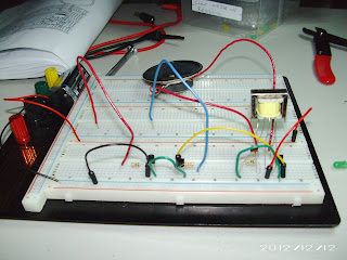
AND gate
Both inputs not connected: gate closed

Both inputs connected: gate open

X input connected and Y input disconnected: gate closed

X input disconnected and Y input connected: gate closed

NAND gate
Both inputs connected: gate closed

Both inputs disconnected: gate open

X input connected and Y input disconnected: gate open

X input disconnected and Y input disconnected: gate open

Elenco's PK-201 Experiment #47: Neither This NOR That

This is the OR gate circuit, but with added components to make a NOR gate. Here, the blue wire is the X input and the red wire is the Y input. The LED's (right and left) represent the outputs. For the NOR gate to be open, both X and Y have to have no input (9v) -- the right LED is on. If either inputs (X or Y), have an input of 9v then the gate stays closed -- right LED is off.
A third type of gate (not shown) is called a NOT gate or inverter that is just the opposite of its input. So, if the input is low, the output is high. And, if the input is high the output is low.
The combinations of resistors and transistors that create different logic gates such as OR, NOR, and NOT, to name a few, are the basic building blocks for computers.  
X and Y have input right-LED off: gate closed


X has 9v input Y has no input right-LED off: gate closed


X has no input Y has 9v input right-LED off: gate closed


X and Y have no input right-LED on: gate open


Schematic Symboles

Elenco's PK-201 Experiment #46: This OR That

This circuit is a digital circuit called an OR gate. The loose wires in the circuit act as inputs, and the LED is the output. The red wire is X input and the Y input is the yellow wire. The LED will be lite if both or either wire is receiving a 9v input. That is why the circuit is called an OR gate if either input is true then the gate opens. Digital circuits are circuits that have only two states, such as high-voltage/low-voltage, on/off, yes/no, and true/false.
X and Y have 9v inputs LED is on

X has 9v input Y has no input LED is on

X has no input Y has 9v input LED is on.

X and Y has no input LED is off.